 Click for larger image
 |
 Click for larger image
 |
In 1953 the "square top" carburetor was replaced with CARTER models E7T1 and E7T2 which housed their own throttle plate. These carburetors, in turn, sat upon a separate sandwich type governor that was used to regulate maximum engine speed. The exceptions to this rule are found on a few Power-Wagons manufactured from 1953 through 1958. These trucks, when special ordered with the mechanical engine governor option, were again fitted with the old E7S1 "square top" carburetor with integral velocity governor. The mechanical governor assembly ceases to exist in parts manuals after 1958. It is apparent that the mechanical engine governor was designed to work only with the velocity type carburetor governor and only on the 230 c.i. L-head engine.
 Click for larger image
 |
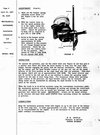
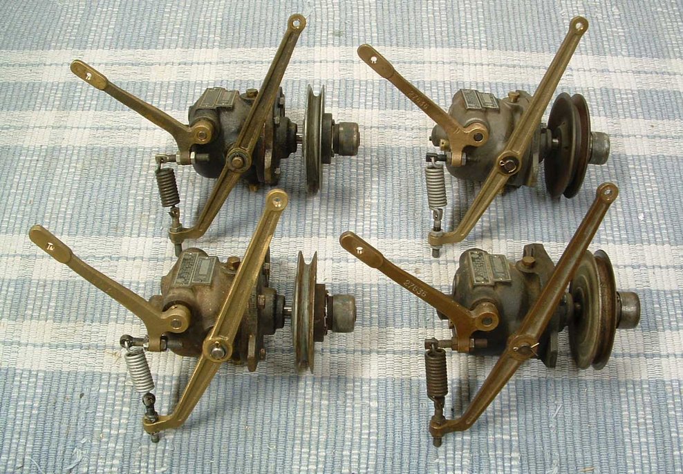
On the free end of each of these levers is a flyweight. These flyweights assure that, as the rotational speed of the shaft increases, the levers swing outward in reaction to the increase in speed. Centrifugal force from the combined rotation of the shaft and inertia of the flyweights creates force upon the levers and allows them to control movement of other components within the governor through leverage. This leverage is transmitted out of the governor through a rockshaft to which is attached a lever arm. This arm controls movement of a telescopic linkage assembly ultimately connected to a carburetor throttle lever, which controls the position of the throttle plate located in the carburetor's integral velocity governor.
As the rotational speed of the engine increases, the resulting centrifugal force created within the governor causes the throttle plate in the integral velocity governor of the carburetor to close via the resulting movement of the interconnected governor lever arm and linkages. In short, as the engine speed increases, the governor closes the throttle slowing the engine. This centrifugal force increases proportionally as the engine speed increases.
With a governor operating simply as described above, the engine would be allowed, or "governed" to run only at idle. Any increase in engine speed would be met by an immediate reaction from the governor causing the throttle to close.
An additional feature of the governor allows for the regulation of engine speed above idle. This is achieved by the use of a spring. This main governor spring is attached by one end to the external levers and linkages of the governor. Its other end is attached to a mounting point. The spring is oriented in such a way as to provide opposing force to the centrifugal force created within the governor.
 Click for larger image
 |
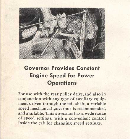
On some governed equipment, such as an engine providing power for a welder for instance, only one set speed of rotation is desired, so the mounting point that the spring connects to is fixed at a permanent location. This desired speed is determined by the amount of power needed to propel the equipment for its intended purpose. In the case of a Power-Wagon driving a tail shaft with the potential of operating various forms of farm and industrial equipment, the need exists for variable governed engine speed in order to match the requirements of the particular equipment at hand.
This adjustable feature is provided for in the original King-Seeley and Pierce and mechanical engine governors through a manual adjustment of the tension on the mainspring. This is accomplished by increasing and/or decreasing the static length of the spring via the location of an adjustable mounting point.
The location of the mounting point is altered through a combination of linkages connecting it to a dash control speed selector Lever mounted to the underside of the dash within the truck cab. Moving the control lever, in such a way to cause tension on the mainspring to increase, results in a higher governed engine speed. Moving the control lever, to cause tension on the mainspring to decrease, results in a lower governed engine speed.
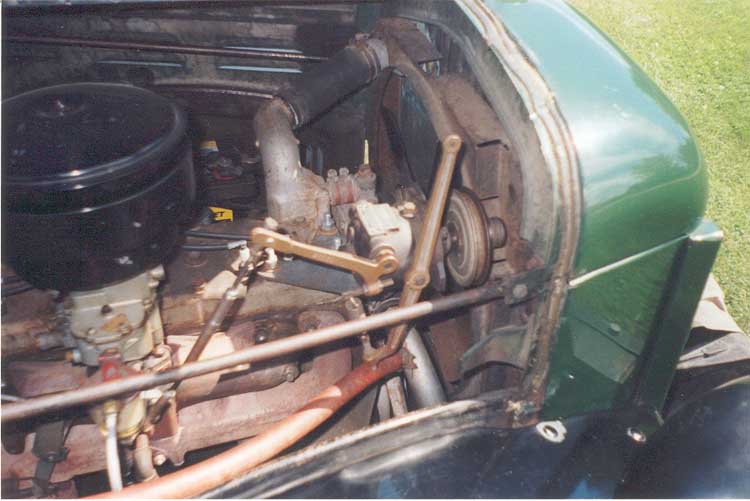
One final feature of the King-Seeley and Pierce governors, as found on the Power-Wagon, sets them apart from most of the others. This unique feature is found in the driven v-belt pulley mounted to the mainshaft of the governor. This pulley can be easily disengaged from the governor mainshaft by an integral dog clutch. This allows it to free wheel as required in order to use the truck for transportation on a highway. With the pulley freewheeling, the idle governor no longer has any influence over engine operation or speed.